

Creating a CUWIN Modbus RTU Master with NModbus
NModbus is a free and open source implementation of the Modbus protocol for the .Net Framework and .Net Compact Framework. This blog post will describe how to get started using NModbus with the CUWIN.
After downloading and extracting the NModbus binaries from the repository, there will be two folders inside the "bin" folder: "net" and "netcf". "net" is for the .Net Framework, and "netcf" is for the .Net Compact Framework. The CUWIN is a .Net Compact Framework device, so to use NModbus in a CUWIN project, simply add a reference to the "Modbus.dll" file in the "netcf" folder.
Add a using declaration to the source file to contain the Modbus Master code.
using Modbus.Device;
Initialize a new ModbusSerialMaster:
// Open COM1 with a baud rate of 115200
_serialPort = new SerialPort("COM1", 115200);
_serialPort.Open();
// Create a new Modbus RTU Master using _serialPort as the communication channel
_modbusMaster = ModbusSerialMaster.CreateRtu(_serialPort);
_modbusMaster.Transport.ReadTimeout = 500;
_modbusMaster.Transport.WriteTimeout = 500;
_modbusMaster.Transport.Retries = 0;
Then call any of the given methods to query a Modbus slave:
bool[] ReadCoils(byte slaveAddress, ushort startAddress, ushort numberOfPoints);
ushort[] ReadHoldingRegisters(byte slaveAddress, ushort startAddress,
ushort numberOfPoints);
ushort[] ReadInputRegisters(byte slaveAddress, ushort startAddress,
ushort numberOfPoints);
bool[] ReadInputs(byte slaveAddress, ushort startAddress, ushort numberOfPoints);
ushort[] ReadWriteMultipleRegisters(byte slaveAddress, ushort startReadAddress,
ushort numberOfPointsToRead, ushort startWriteAddress, ushort[] writeData);
void WriteMultipleCoils(byte slaveAddress, ushort startAddress, bool[] data);
void WriteMultipleRegisters(byte slaveAddress, ushort startAddress, ushort[] data);
void WriteSingleCoil(byte slaveAddress, ushort coilAddress, bool value);
void WriteSingleRegister(byte slaveAddress, ushort registerAddress, ushort value);
The following sample project demonstrates creating a Modbus Master using the CUWIN CWV2 that monitors and controls a Modbus slave using a CUBLOC CB280 and the Study Board 2. The CB280's digital output on pin P0 is connected to the Study Board's LED0 on the, and an analog input is connected to the Study Board's knob potentiometer, AD1.
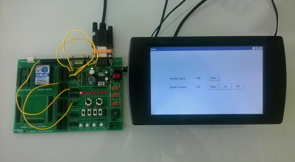
The Analog Input "Read" button will query the CB280 for the value read from its analog input and display it on the form. Turning the knob pot AD1 on the Study Board will change the value read from the analog input.
The Digital Output "Read" button will query the CB280 for the state of the CB280's digital output on pin P0. The Digital Output "On" and "Off" buttons will turn P0 on or off respectively thus turning the Study Board's LED0 on or off.
Recent Posts
-

24/7 Real-Time Technical Support: Launching Our AI Assistant Service!
Hello, this is Comfile Technology. At Comfile Technology, we have always strived to provide the fa …Feb 24th 2026 -

CPi Panel PC Lite Models are Upgrading to 32GB SD Cards
The standard SD card capacity for CPi Panel PC (Lite models) is being upgraded from 8GB to 32GB. Mov …Feb 7th 2026 -

Introducing the New CFNET Field I/O
We are pleased to introduce our new CFNET Field I/O product. This product has been in development f …Jan 31st 2026